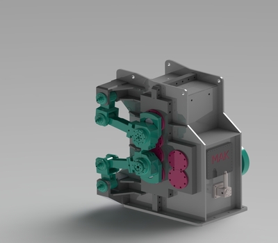
Crank shear

| Location | Components |
| Roughing mill |
|
| Dute | |
Head and tail cropping. Emergency chopping. Cutting to multiple lengh (if any). | |
| |
A-Motor coupling and coupling guard The motor torque is transmitted to the shear body via gear-type coupling. Motor holding brake to prevent oscillation of blade holder while in waiting position.
| |
B- Crank shear Start-stop, crank type with one blade on each blade holder. Bladeholder shafts driven by gears powered by start-stop motor. Input shaft dimensioned to ensure the required inertia for cutting (i.e. a flywheel is installed if required). Fabricated steel housing, sealed for oil tightness. Transmission gears in alloy steel, carburized, hardened and ground, mounted on roller bearings. Fabricated steel blade holders and articulated arms. Blades are fastened by screws; blade overlap is adjusted by shims while clearance is adjusted by eccentric pins
| |
C- Plain on board blades Alloy steel, heat treated by hardening and anealing. Locked to the bladeholder by screws.
| |
D- Inlet / outlet equipment Entry and exit conveying troughs in fabricated steel structure. The entry trough is also fitted with motorized rollers to prevent scratching.
| |
E- Motor baseplate Fabricated steel structure.
| |
F- Shear guard Fabricated steel structure, including supporting columns, fixed and manually movable sliding protection panels with perforated plate and idle wheels, top and bottom runways.
| |

